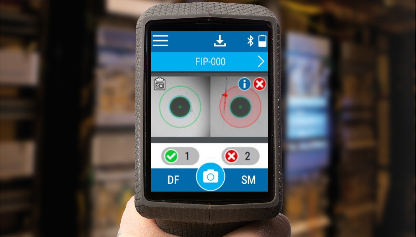
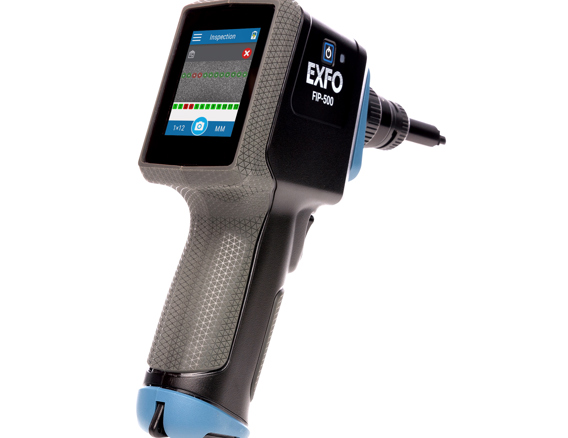
Inspection of connectors endfaces
Field technicians inspect connector endfaces to identify any contamination, defects and scratches against established standards like IEC/IPC or user-defined criteria.
Automated and accurate pass/fail diagnostics for connectors can greatly accelerate field operations while ensuring that the no. 1 cause of network failures (i.e., dirty or damaged connectors) has been dealt with. Specialized tools such as fiber- inspection probes, and cleaning kits are indispensable for this purpose.
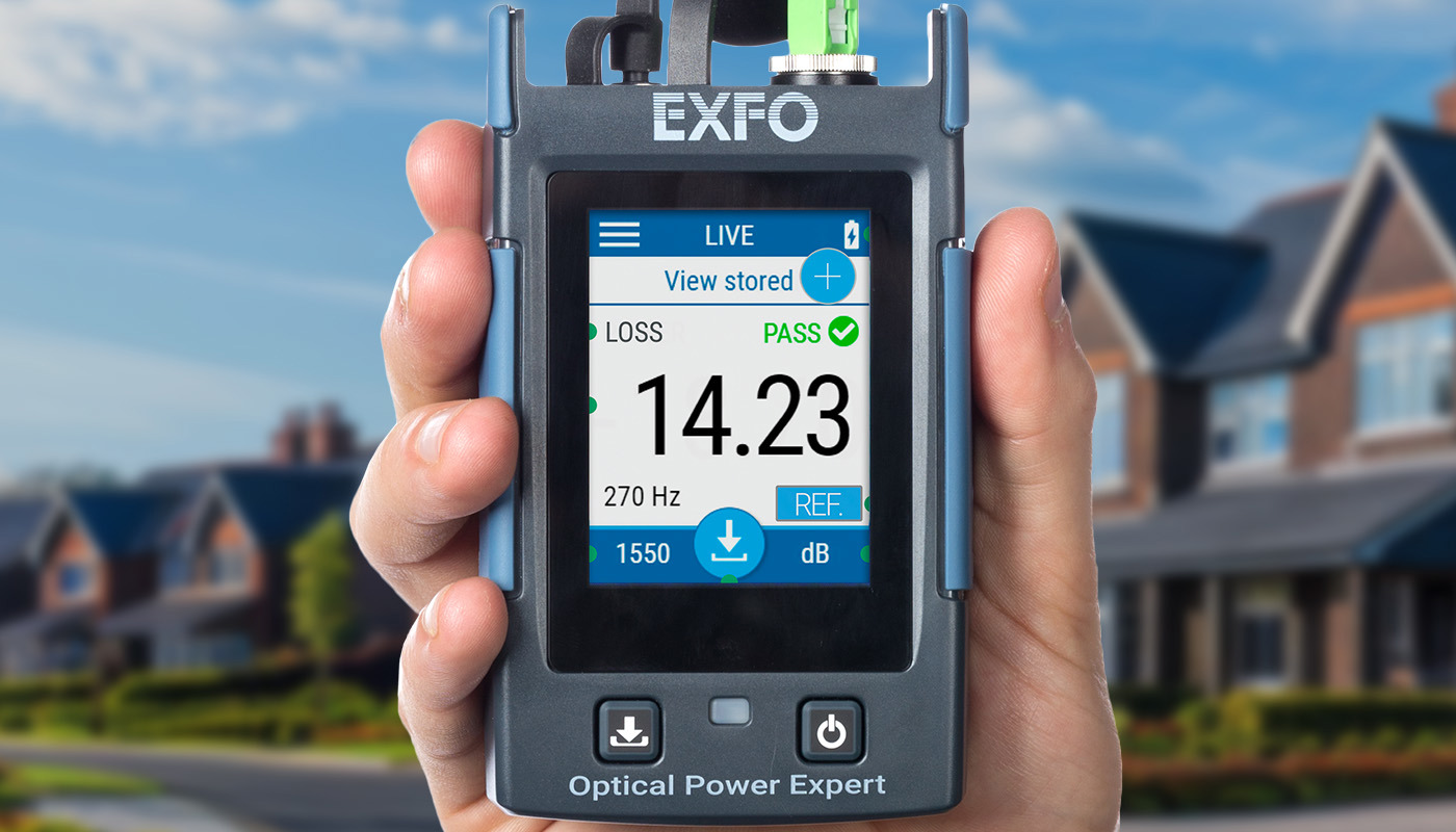
Monitoring insertion loss (IL)
Irrespective of fiber types and wavelengths, monitoring IL remains crucial across varied bending angles. While the angles may vary, the underlying behavior remains consistent. Excessive loss is generated through fixed-angle bending, potentially leading to identification inaccuracies.
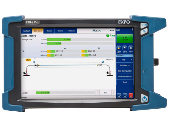
IL can be tested with an optical power meter, an optical loss test set (OLTS) or an optical time-domain reflectometer (OTDR).
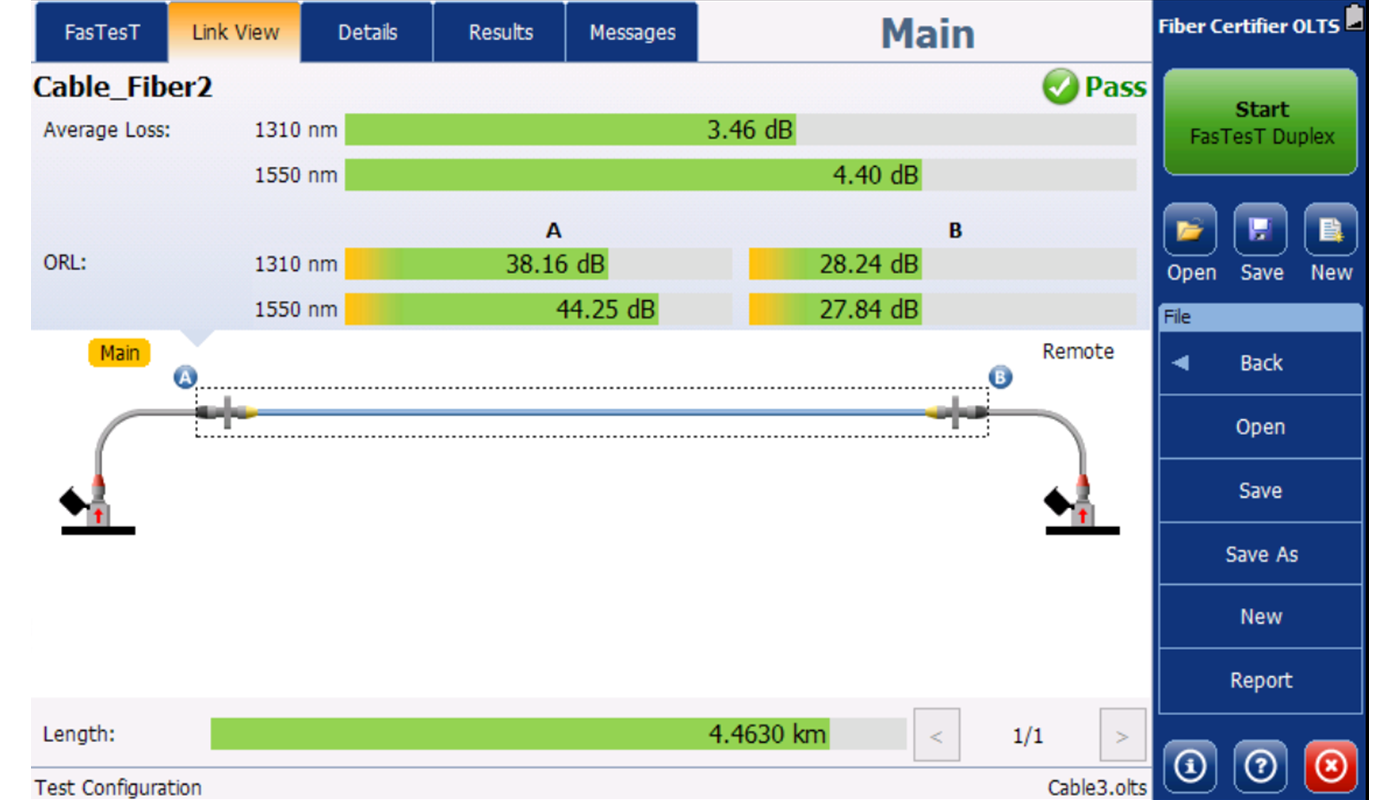
Assessing optical return loss (ORL)
Arising from the reflective properties of network components like fiber, mechanical connections or substandard splices, ORL assumes significance due to its potential impact on transmitter performance and service quality.
ORL can be quantified using a backreflection tester or an OLTS equipped with a backreflection option.
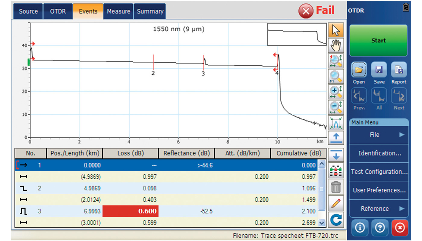
Characterizing the optical link and elements
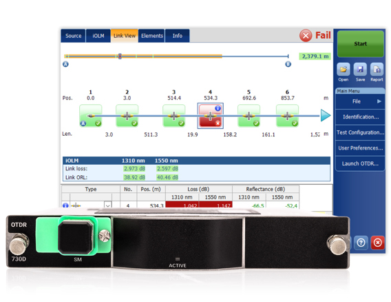
OTDRs are pivotal in the comprehensive characterization of fiber links, facilitating the measurement of loss, reflectance, and attenuation across all network connections, splices, and splitters. Additionally, OTDRs offer precise distance measurements.
Automated OTDR threshold setting, multipulse acquisitions and analysis (as performed by iOLM) can provide precise icon-based mapping of all elements on the link at the push of a button, avoiding the risk of human errors.
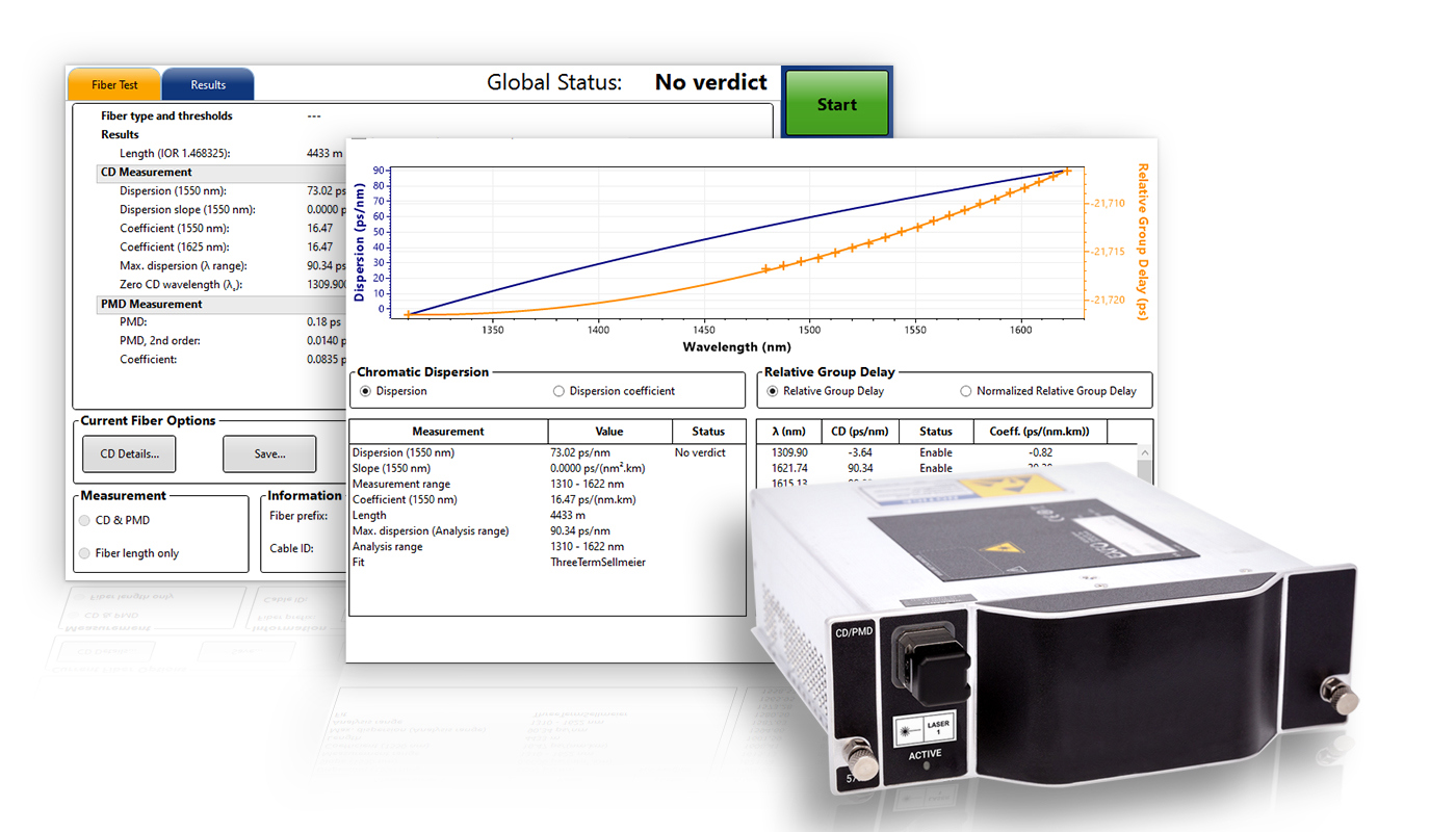
Analyzing dispersion
Chromatic dispersion (CD) and polarization mode dispersion (PMD) can both lead to an increase in bit error rates. CD is pulse broadening due to different wavelengths inside a pulse of light traveling at different speeds. PMD is pulse broadening caused by the differences in propagation velocities for different polarization states. CD increases linearly with distance (e.g., doubling the distance doubles the CD), and PMD increases with the square root of the distance (e.g., multiplying the distance by four doubles the PMD).
There are two types of test solutions available in the industry:
- Dual-ended testers, which require a source at one end and a detector at the other.
- Single-ended testers, which combine the source and the detector within a single instrument.
According to the ITU-T G.650.3 guidelines, it is not necessary for this measurement to be conducted from both ends of the link. The single-ended approach therefore provides reliable measurements with half of the resources dispatched to the field, significantly reducing operational expenses.
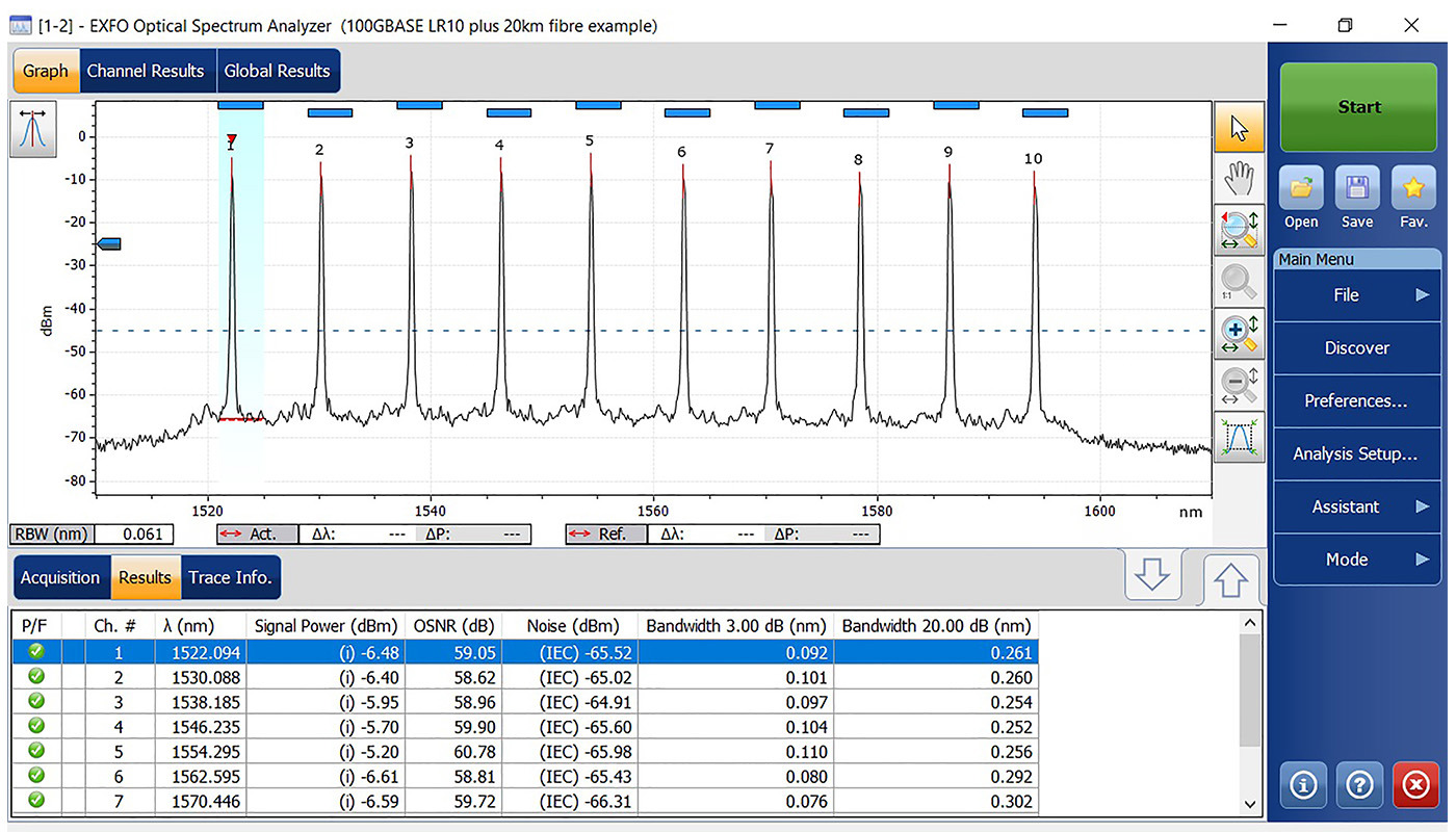
Evaluating spectral attenuation
Attenuation denotes power loss attributed to various scattering and absorption phenomena. The objective is to gauge the transmitted intensity of a spectral pulse of light across multiple wavelengths to calculate attenuation rate accurately.
Spectral attenuation can be tested with an optical spectrum analyzer (OSA).
Ähnliche Produkte

AXS-120 - Last-Mile/Access-OTDR
Das kleine, aber feine AXS-120 profitiert von der anerkannten Präzision, Zuverlässigkeit und Robustheit der OTDRs von EXFO in einem kompakten Formfaktor.

FTBx-570 - Single-Ended Dispersion Analyzer
Branchenweit einzige Lösung für schnelle Single-Ended CD/PMD-Tests
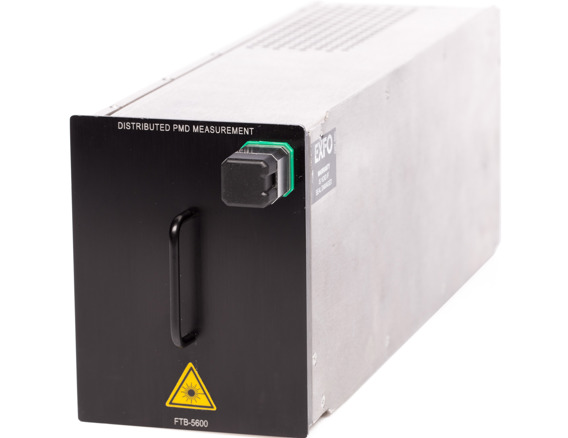
FTB-5600 - Distributed PMD analyzer
The only distributed PMD analyzer on the market, offering simplified PMD assessment for identification of faulty sections on links.
FTBx-945 Telco OLTS
Multifunction optical loss test set (OLTS) for the FTB-2 and FTB-2 PRO platforms

FTBx-720D - LAN/WAN access OTDR
Purpose-built construction OTDRs for everyday field testing in any access network. With an intelligent Optical Link Mapper (iOLM) application for both singlemode and multimode testing, this is the most automated and intelligent troubleshooting tool for FTTA, LAN and data centers.
FTBx-730D - PON FTTx/MDU OTDR
Reibungslose Charakterisierung von Splittern in PON FTTx- und MDU-Anwendungen.
FIP-500 - Faserprüfmikroskop
Branchenweit schnellste Inspektion von Einfaser-, Duplex- und Mehrfaser-Verbindern mit der zuverlässigsten Ergebnisbewertung. Autonomes und vollautomatisches Prüfmikroskop für Tests ohne Tastendruck über den gesamten Arbeitstag ohne lästiges Akkuladen oder Ergebnisexport.
FTBx-5235 - Optical spectrum analyzer
New, compact OSA designed to measure channel power and wavelength, characterize Remote PHY deployments and analyze DWDM networks